The specific tandem propeller arrangement discussed will be two propellers operating one behind the other on the same shaft with the same rotational speed and direction of rotation. Results performed in ANSYS.
Pdf Design Optimization Of Automotive Propeller Shafts
2003 described a series of model- and full-scale trial measurements on a Kappel propeller.
. An overall shaft design procedure is presented including consideration of bearing and component mounting and shaft dynamics for transmission shafting. The composite drive shaft made up of high modulus material is designed by using CAD software and tested in ANSYS. Types of Propeller shafts.
Shaft weights buckling. The designed propeller shaft is below Fig 51 Propeller Shaft Propeller Shaft Model and Mesh The modeling of propeller shaft using Catia. The calculations should be carried out according to the rules mentioned in the IRS Rules.
Dp 125 x 400135 dp 500 mm Design of Intermediate Shaft d The intermediate shaft is subjected to bending. The specific design procedure discussed will be for the tandem unit operating in uniform. ReInove the propeller shaft froIn the truck by taking out four capscrews at each end holding the flange type bearings to the fitting yokes being careful not to let the flanged bearings fall off and perInit foreign Inatter to enter the rollers.
Design of Propeller Shaft dp Since the propeller shaft is subjected to both bending moment due to propeller weight and twisting moment diameter of propeller shaft dp 25 extra then the designed by pure torsion. An overall shaft design procedure is presented including consideration of bearing. ClaInp the propeller shaft in a vise and.
Solid and hollow Propeller shaft design. Design and development of compositehybrid propeller shaft using fiber reinforced plastic material FRP. Manual Calculations Marine propeller shaft design is to be done based on torsion and bending provided the engine and gearbox parameters.
The systematic and methodical design process followed in this case example illustrates the theoretical models usable for design engineering Eder and Hosnedl 2008 2010. Free Shipping Lowest Prices. Get the Right Prop Fast.
Third is to fabricate two propeller shafts one made of only GlassEpoxy and the other an Hybrid shaft GlassEpoxy and Aluminum and the fourth is to perform the static test on the fabricated shafts. 2 Option two using 900mm upper and lower V-shaped anvil. Ad Our Reliable Bearing Systems Are Water-Lubricated Saving You Money And Hassle Long Term.
Features And Design Of Propeller Shaft Forging Process. DisasseInble propeller shaft joint using follow ing procedure. Three forged schemes have been determined according to the shape of the forged and the conditions of the existing hydraulic presses in the factory.
Our Bearings Are Easy To Install Lightweight Have Industry Leading Wear Life Guarantees. The propeller shaft is designed by required dimensions into the modeling software Catia V5. The term shaft usually refers to a component of circular cross section that rotates and transmits power from a driving device such as a motor or engine through a machine.
A propeller shaft drive shaft driveshaft driving shaft or cardan shaft is used for transmitting torque mainly in automobiles and in ships. To check the design of propeller shaft mathematically with a conventional material. This process is only necessary.
Shafts can carry gears. Most shafts will transmit torque through a portion of the shaft. Andersen et al 2005.
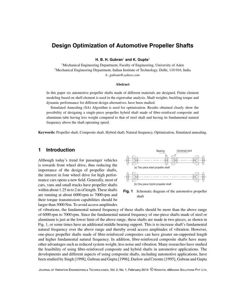
Finite element modeling based on shell element is used in the eigenvalue analysis. A procedure is outline in this report for the design of tandem propellers. OEM Aftermarket Props 20-60 Off.
Ad 20-60 Off All Props. Our main aim is to study its design procedure along with finite element analysis some important parameter will be obtained. This process is only necessary.
F Process of assembling the propeller shaft thrust bearings to be done by Stage Barge personnel. The design process is such that the propeller blades and their winglets addition are designed as a single integral curved blade Andersen and Andersen 1986. The methodology followed for the automation of the propeller shaft designing process is as follows.
The geometry of the propeller shaft is designed in Catia V5 is imported to the analysis software in the IGES format. 1 Option 1 using 800mm upper flat anvil and lower platform compaction process. In this paper six automotive propeller shafts made of different materials are designed.
Free Shipping Lowest Prices.
How Sighting Boring And Alignment Of Ship S Propeller Shaft Is Done
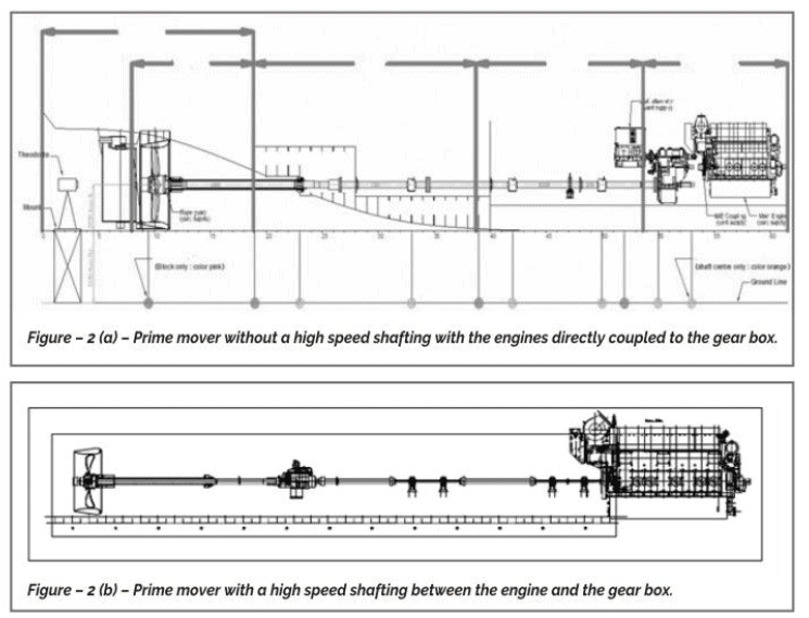
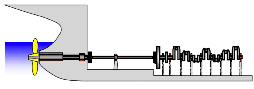
Marine Propeller Shafting And Shafting Alignment Part 1 Thenavalarch

Cad And Finite Element Models Of The Propeller Shaft A Cad Model And Download Scientific Diagram
Propeller Shaft Bearings Various Type

Propeller Shaft Arrangement 6 Download Scientific Diagram

Propeller Shaft Arrangement 6 Download Scientific Diagram

Schematic Diagram Of The Propeller Shaft For A Rear Wheel Driving Vehicle Download Scientific Diagram

Propeller Shaft Function Types Components And Requirement
0 comments
Post a Comment